I want to do some battery powered sensing with an esp8266 - and to get a good battery life, I need to use the 'deep sleep' mode. Deep sleep requires a reset (including a bootloader and some radio calibration) to wake from. I decided to test how different pins behave when in deep sleep or undergoing a reset.
Schematic
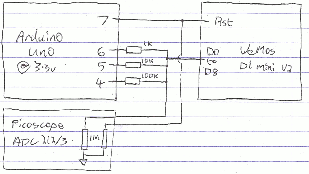
By switching the Arduino Uno outputs between high, low and high impedance, we can test a variety of pull up and pull down values applied to the pins of the module.
Notes
- These tests were performed on a 'WeMos D1 Mini V2' module carrying an 'ESP-12F' module carrying the esp8266. The modules include some pull and and down components. I've tried to note these below.
- As the picoscope has a 1 MΩ input impedance, a 100 kΩ pull up to 3.3v with no other load makes a resistor divider with a 3v output voltage.
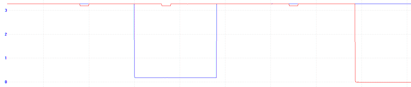
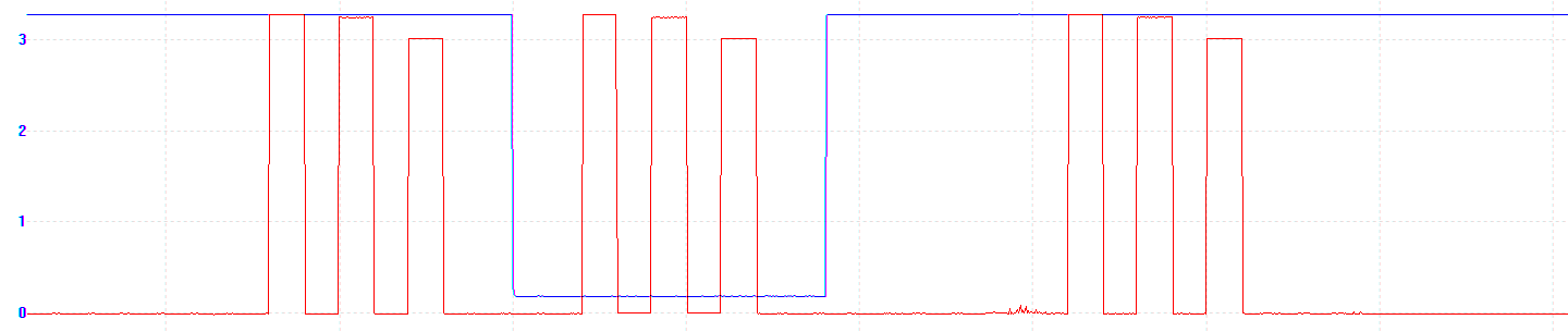
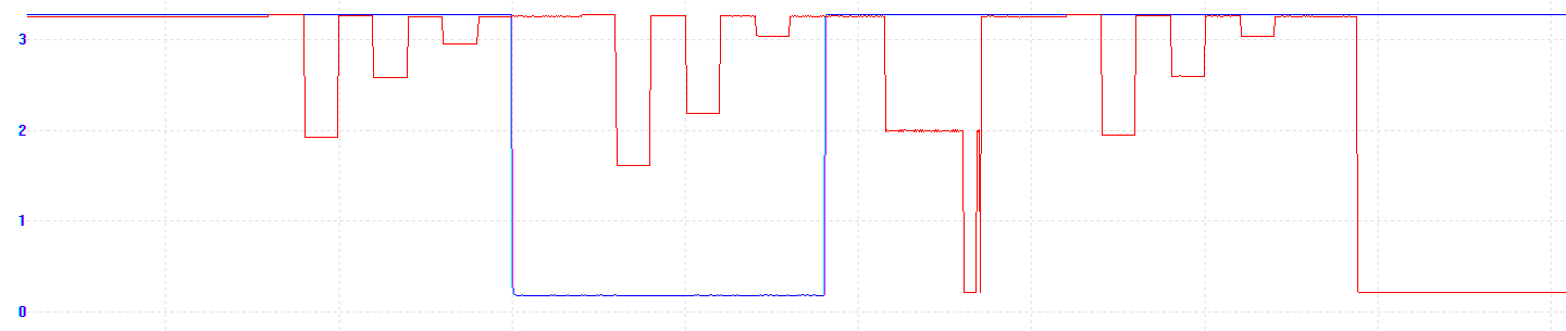
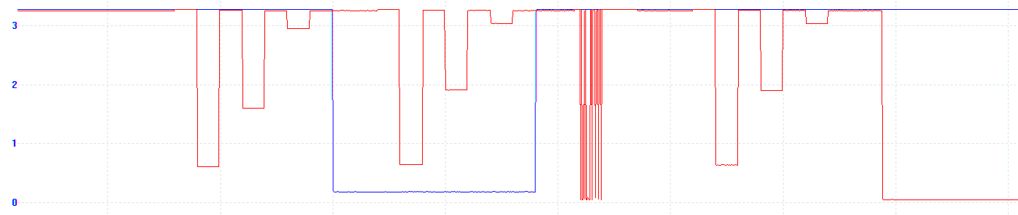
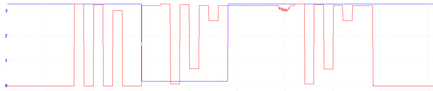
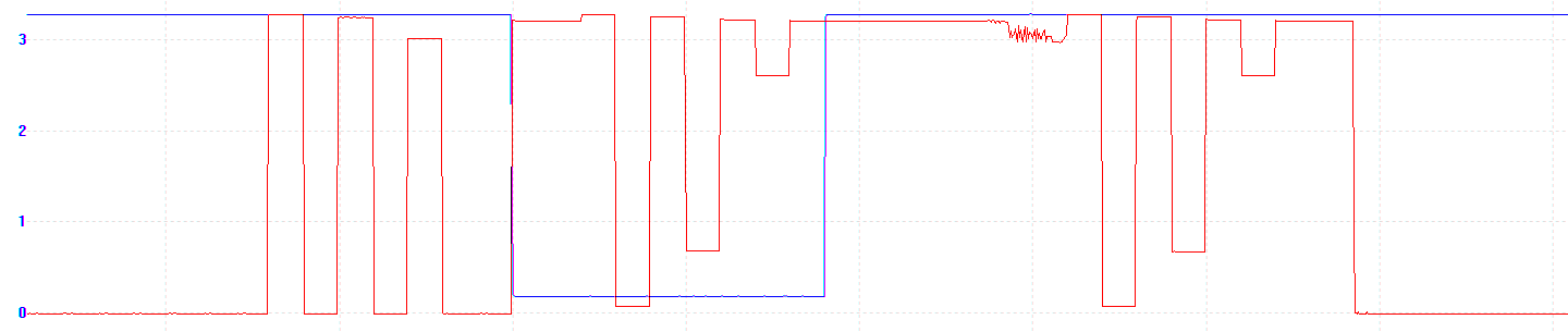
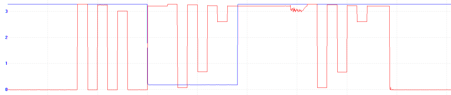
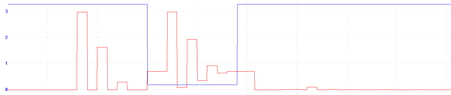
- The timebase for the charts below is 100 milliseconds per division, and the vertical scale is in volts. The blue line is the reset signal and the red line is the pin being tested.
- The gap between 'Reset pulled low' and 'Chip restarting' is intentional, I put it in because of the GPIO0/GPIO2 bootloader behaviour (you'll see it when you scroll down).
- The two test programs are at the end of this post. I programmed the esp8266 using Arduino board support package 2.3.0 - as some of the behaviour is probably bootloader/SDK dependent, YMMV.
Stimulus circuit output without ESP8266

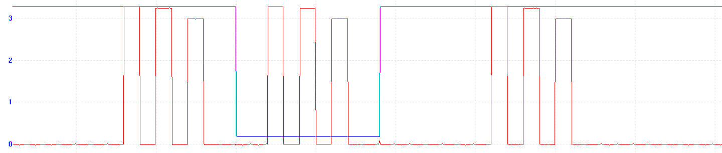
WeMos mini pin D0 / GPIO16
Special function - timer reset when in deep sleep
WeMos mini pin D1 / GPIO5
WeMos mini pin D2 / GPIO4

WeMos mini pin D3 / GPIO0
10k pullup on D1 mini schematic, and reset circuit connection to DTR/RTS/RST
WeMos mini pin D4 / GPIO2
10k pullup on D1 mini schematic, blue LED & 470 ohm resistor on ESP-12F
WeMos mini pin D5 / GPIO14
WeMos mini pin D6 / GPIO12
WeMos mini pin D7 / GPIO13
WeMos mini pin D8 / GPIO15
10k pulldown on D1 mini schematic
Summary
It takes 300ms from the reset pin rising edge for the user's program to start running (at least when deep sleep mode WAKERFDEFAULT is used)
Pins' values while in deep sleep, reset, and during restart are unaffected by the value the pin was set to before deep sleep.
Individual pins behave differently, and their behaviours are as follows:
| D1 mini pin | GPIO | Deep sleep | Reset held low | During restart | Note |
|---|---|---|---|---|---|
| D0 | 16 | strong high | strong high | strong high | special role - wake from deep sleep |
| D1 | 5 | high impedance | high impedance | high impedance | |
| D2 | 4 | high impedance | high impedance | high impedance | |
| D3 | 0 | ~500 ohm high? | ~875 ohm high? | ~500 ohm high? | Pull up resistor & controls boot behaviour |
| D4 | 2 | ~5k pull up | ~5k pull up | ~5k pull up | Pull up resistor & blue LED |
| D5 | 14 | high impedance | weak high | weak high | |
| D6 | 12 | high impedance | weak high | weak high | |
| D7 | 13 | high impedance | weak high | weak high | |
| D8 | 15 | high imp & 10k pull down | weak high & 10k pull down | strong low | Pull down resistor |
Program for Uno to provide timed pull up / pull down
const int led = 13;
const int reset = 7;
const int oneKohm = 6;
const int tenKohm = 5;
const int hundredKohm = 4;
const int HIGH_impedance = INPUT;

void setup() {
  // put your setup code here, to run once:
  pinMode(reset, OUTPUT);
  digitalWrite(reset, HIGH);
  pinMode(led, OUTPUT);
  digitalWrite(led, HIGH);
}

void loop() {
  digitalWrite(led, HIGH);
  digitalWrite(reset, HIGH);
  delay(5000);
  digitalWrite(led, LOW);

  cycleLoads();
  delay(20);
  digitalWrite(reset, LOW);
  delay(20);
  cycleLoads();
  delay(20);
  digitalWrite(reset, HIGH);
  delay(120);
  cycleLoads();

}

void cycleLoads() {
  pinMode(oneKohm, HIGH_impedance);
  pinMode(tenKohm, HIGH_impedance);
  pinMode(hundredKohm, HIGH_impedance);
  delay(20);

  cyclePinUpDown(oneKohm);
  cyclePinUpDown(tenKohm);
  cyclePinUpDown(hundredKohm);
}

void cyclePinUpDown(int pin) {
  pinMode(pin, OUTPUT);
  digitalWrite(pin, HIGH);
  delay(20);
  digitalWrite(pin, LOW);
  delay(20);
  pinMode(pin, HIGH_impedance);
}
Program for the esp8266:
#include <ESP8266WiFi.h>

void setup() {
  pinMode(0, OUTPUT);
  digitalWrite(0, 0);
  pinMode(2, OUTPUT);
  digitalWrite(2, 0);
  pinMode(4, OUTPUT);
  digitalWrite(4, 0);
  pinMode(5, OUTPUT);
  digitalWrite(5, 0);
  pinMode(12, OUTPUT);
  digitalWrite(12, 0);
  pinMode(13, OUTPUT);
  digitalWrite(13, 0);
  pinMode(14, OUTPUT);
  digitalWrite(14, 0);
  pinMode(15, OUTPUT);
  digitalWrite(15, 0);
  pinMode(16, OUTPUT);
  digitalWrite(16, 0);

  delay(1000);

  ESP.deepSleep(0, WAKE_RF_DEFAULT);
}

void loop() {

}