Ever wondered how cheap digital verniers are able to produce good precision at very low prices? I did, so I took one apart.
I'm not the first person to look at this - Grant Trebbin has some photos of a teardown, and has done a good job of finding patents like US5068653 Capacitive displacement measuring device with t-shaped scale coatings; Nick Müller has inspected one with an oscilliscope and Anyi Instrument Co have posted some info on how the sensors work.
Turns out they use capacitive sensing - there's a thin PCB hidden under a label on the shaft of the vernier:
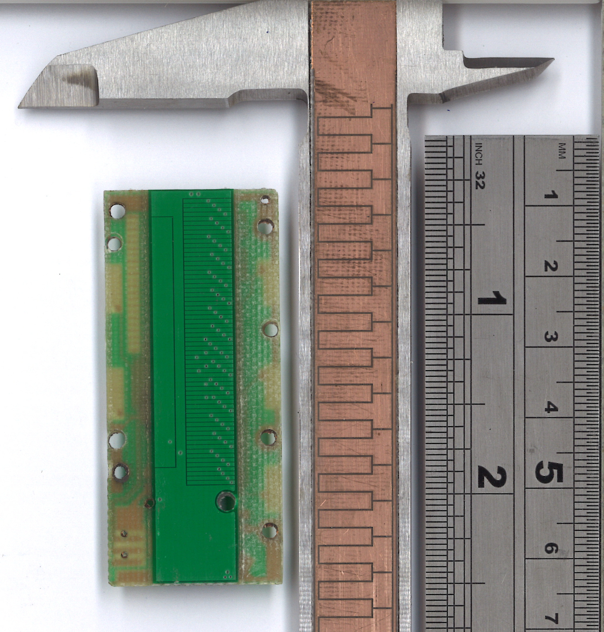
The green PCB on the left is for the slider. Every eighth bar in the densely striped section is connected together - i.e. the first, 9th and 17th bars are connected together, as are the 2nd, 10th and 18th, and so on.
I measured the distance between the PCBs on the slider and shaft using a cheap feeler gauge; the spacing was about 0.35mm ±0.05mm.
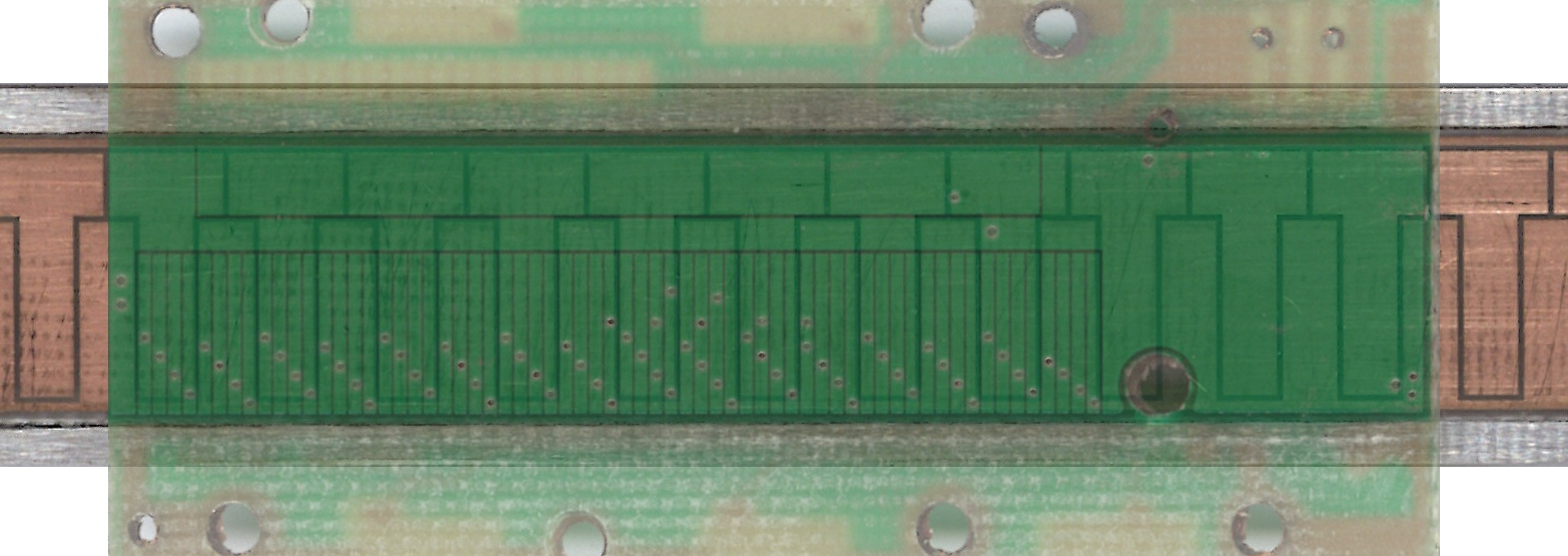
Based on the 600 dpi scan above, the T sections on the shaft and the densely striped section is about 250 mm², and each of the eight banks of stripes has an area of 31 mm². The return strip has an area of about 95 mm². The comb overlaps the ground plane by about 43mm²; while that's obviously the same order of magnitude as the return strip, they don't seem to have been made precisely the same surface area.
So each of the eight stripes has a capaitance of about 0.78 picofarads while the return strip has a capacitance of about 2.4 picofarads - taken in series, that's about equivalent to 0.588 picofarads. That's very small. For example, the ADC on an ATMega (like an Arduino Uno) has an input capacitance of ~14pF. It's also smaller than the input capacitance of my oscilliscope. But some capacitive sensors claim to be able to measure femtofarad capacitance changes - the AD7745 claims an accuracy of 4 femtofarads, and the AD7147 a sub-femtofarad output noise.
The stripes in the densely striped section are about 0.63mm wide, and the vernier's precision is 0.01mm. That means, if my estimate of a 588 femtofarad capacitance is correct, the capacitance measurement is precise to about 9 femtofarads.
If you attach an oscilliscope to the eight sets of bars in the striped section, and the return bar, here's what you see:
( Raw data CSV )
Of course, the oscilliscope's probes introduce a certain extra resistance and capacitance. Several tens of picofarads of capacitance and 10 MOhms of resistance, both to ground, would be typical.
Unfortunately, I didn't keep track of exactly which channel was which - but Nick Müller's oscilliscope work, linked above, shows us the inputs that are inversions of one another are four bars apart in the striped section. Also, as I used an 8-channel oscilliscope, I could only track the output and seven inputs. So the line marked "Input 5" is just input 6 flipped over.
Let's zoom in on that first section.
Nick Müller's trace shows the output spiking high and low in equal amounts - I assume the fact mine doesn't is because it's clamped to the battery voltage by a diode, or something similar. The low spikes have a width of about 0.01ms - presumably something pulls the output to the center value after the spike has been measured.
The sensing cycle appears to take differential measurements between of bars; in the diagram above a pair of lines either becomes narrow or becomes wide. The sensing cycle appears to rotate between all channels narrowing (widening); three of the four channels widening (narrowing) while the remaining channel is fixed; and three of the four channels widening (narrowing) while the remaining channel does the opposite.
A complete sensing cycle takes around 1.7 milliseconds - although the system may average multiple sensing cycles to reduce noise. The AD7147, linked above, takes 6-36ms to sample 8 inputs (depending on how precisely you want to measure).
The comb on the vernier shaft has a tooth pitch of 5mm. In other words, if the slider instantly moved 5mm, it would be undetectable, or 'ambiguous'. So what's the top speed you could go at? Depends (a) how much sample averaging you need and (b) if you can measure while moving. Assuming you can measure while moving, if a measurement takes 1.7ms and you want four per ambiguity step (i.e. a measurement every 1.25mm) you could go as fast as 0.7 m/s - but if it takes 66ms to make such a measurement, your speed would drop to 0.035 m/s. Or maybe the measurements work some other way and I'm completely wrong!